
Multi-Floor Building Robot Deployment, Navigation Layers and the Four Vertical Constraints
At a glance: Floor-to-floor movement looks like a mobility problem and is actually a software problem. This guide separates the navigation stack into four evaluable layers, sets out the four vertical constraints that cap fleet sizing, and gives a five-test live protocol run during real traffic.
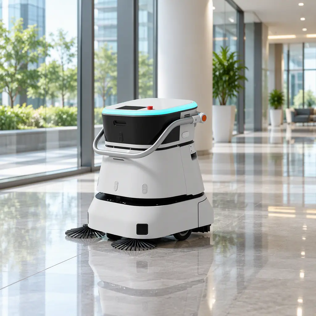
Floor-to-floor movement looks like a mobility problem and is actually a software problem. The robot can drive; the question is whether the navigation stack, the map and the building's vertical transport can agree on where the machine is and when it is allowed to move.
This guide separates the navigation software stack into the components a buyer can evaluate, explains what multi-floor operation adds to each one, and sets out the four vertical constraints that decide fleet sizing before any horizontal arithmetic is applied.
The Navigation Stack, Layer by Layer
"SLAM navigation software" is often treated as one thing. It is four functions running at different rates and failing in different ways. Understanding the division matters because vendors bundle them differently, and a weakness in any single layer limits the whole machine.
| Layer | Function | Update Rate | Typical Failure |
|---|---|---|---|
| Localisation | Determines where the robot is on the map, continuously | 20-50 Hz | Position drift in repetitive or feature-poor space (long corridors, glass walls, empty halls) |
| Mapping | Builds and maintains the representation of the environment | Offline / infrequent | Stale map after layout change; zone geometry no longer matches reality |
| Path planning | Computes a route from current position to task target | 1-10 Hz | Plans through transient obstacles; suboptimal coverage patterns |
| Obstacle avoidance | Reacts to dynamic objects inside the safety envelope | 10-40 Hz | Over-conservative behaviour in crowds; deadlock in narrow aisles |
The rate column is not trivia. Localisation running at tens of hertz while obstacle avoidance runs slower creates a specific failure mode: the robot knows where it is but reacts late to a person stepping out. Both functions being fast is not sufficient, their relative timing determines behaviour in dense environments. When evaluating a machine, ask which functions run on dedicated compute and which share a single board, because shared compute under load is where latency appears in the field.
What Multi-Floor Operation Adds
Adding vertical movement changes the problem in four distinct ways, and each one has a different owner.
Map topology becomes a graph, not a plane
A single-floor map is a two-dimensional occupancy grid. A multi-floor map is a set of grids connected by vertical links, where each link has traversal conditions. The lift must be present, the doors open, the destination floor selected. The robot must hold a coherent model of which floor it is on and dispel any ambiguity about the connection between them, because localisation across floors from geometry alone is impossible: two identical floors look identical to a lidar. The resolution is that the vertical transition must be treated as an explicit state change with its own confirmation, not as continuous navigation.
Vertical transport becomes a shared, contested resource
A service lift is not dedicated infrastructure. It carries people, deliveries and waste. A robot that must reach floor 6 competes for a resource whose availability it does not control, and whose occupancy pattern varies by hour. This is the single largest source of schedule variance in multi-floor deployments, and it is a building-interaction problem rather than a robot capability problem.
Coverage arithmetic changes
On a single floor, productive coverage rate is roughly constant. Across floors it is not, because every transition consumes time that produces no cleaned area. A unit that achieves 1,400 m² per productive hour on one level may deliver substantially less across three levels once lift waiting is included. The loss is not the transit time itself, which is short, but the variance around it.
Safety state must persist across the transition
Inside a lift, the robot is in a confined, shared, moving space. The safety envelope that applies in an open hall is not appropriate there. Machines that handle this well treat the transition as a distinct operational mode with its own envelope; machines that do not tend to either block doors or trigger unnecessary stops that strand them between floors.
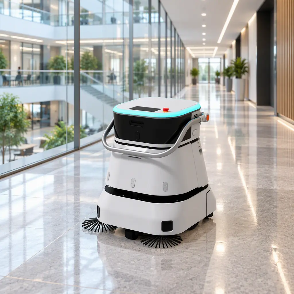
The Four Vertical Constraints That Decide Fleet Sizing
Before calculating how many units a building needs, establish whether the vertical infrastructure can support the intended schedule at all. These four constraints frequently change the answer.
| Constrain | Why It Bites | How to Measure It |
|---|---|---|
| Lift count and dedication | Shared lifts mean the robot cannot reserve capacity; two units may contend for the same car | Count service lifts and record whether any can be dedicated during cleaning windows |
| Lift cycle time | Travel between the two furthest floors, including door dwell, can exceed several minutes | Time a full round trip during the actual cleaning window, not at quiet hours |
| Door and access control | Robot needs credentials for every door on the route, including stairwell and service doors | Walk the intended route and list every controlled opening |
| Charging location | If docks are on one floor only, units burn vertical trips purely to charge | Calculate charge trips per shift; if above one per unit, consider a second dock location |
The charging constraint is the one most often missed. A fleet whose docks sit on the ground floor of an eight-level building will spend a meaningful share of its operating window riding lifts to and from charging. The fix is either distributed docking, which requires electrical work per floor, or accepting a lower effective coverage rate per unit and sizing the fleet upward to compensate. Both are legitimate; choosing neither produces a fleet that consistently under-delivers against its own business case.
Evaluating Navigation Software in a Live Trial
Vendor claims about navigation are difficult to disprove on paper. The tests below are designed to be run in the actual building, with the actual furniture, during the actual shift.
- The glass wall test. Run the machine along a route bounded by glass or mirrors. Localisation that depends on geometric features degrades where the environment is reflective or feature-poor. Watch for hesitation, re-localisation pauses or route deviation.
- The rush hour test. Operate during the busiest hour the site will actually see. A machine that navigates cleanly at 06:00 and stalls at 12:00 will be switched off by staff within two weeks, regardless of specification.
- The layout change test. Move a fixture, a display stand, a partition, a rack end, and observe whether the machine adapts, requires re-mapping of the affected zone, or fails. Ask what the re-mapping cost is in operator time.
- The floor transition test. If the site is multi-floor, watch a full transition with the lift in normal service, not reserved. Measure the elapsed time from arrival at the lift lobby to resumption of cleaning on the destination floor.
- The stale map test. Ask how the site's map is versioned and who owns updates. A map with no owner drifts, and a drifted map is the root cause of most "the robot stopped cleaning the west wing" reports.
Test four is the highest-information test available for multi-floor sites, and it is also the one vendors most often propose to demonstrate outside normal traffic. Insist on running it during service hours. The number that comes out of that test is the number that belongs in the business case.
Recalculating Coverage for Multi-Floor Sites
The practical arithmetic for a multi-floor building differs from the single-floor model, and the difference is entirely in the availability term.
Take a four-level building with 3,200 m² cleanable per level, 12,800 m² total. Assume a single unit achieving 1,400 m² per productive hour, an eight-hour operating window, and a nominal machine availability of 70% derived from docking, refills and drains on a single floor. On one level this yields roughly 7,840 m² per shift, about 3.5 productive hours of the four needed per level.
Now introduce two vertical transitions per shift. If each transition including lift wait averages four minutes with a wide variance, the direct time cost is small, under ten minutes, but the schedule reliability cost is larger, because cleaning windows on each level are fixed by building occupancy. A late transition does not extend the window; it truncates the coverage on the destination floor. The correct treatment is to reduce the availability assumption, not to subtract transit minutes, because the constraint that binds is the window, not the clock. Reducing availability from 70% to roughly 62% for a two-transition shift is a defensible working figure, and it moves the fleet requirement by about one unit across this building.
That single unit is the whole point of running the arithmetic before the purchase order. Our labour cost model provides the underlying input definitions, and the navigation and SLAM guide covers the sensor-level detail behind the layer table above.
Where the Vertical Problem Meets the Portfolio Problem
Multi-floor buildings rarely sit alone. A portfolio with three multi-level sites and nine single-level sites cannot be planned with one sizing formula, because the two building types have different availability profiles and therefore different unit requirements per square metre. Treating them uniformly under-sizes the multi-level sites and over-sizes the single-level ones, and the error compounds across tranches.
The consolidation approach that handles this correctly is described in our guide to managing robots across multiple buildings, which segments by building archetype for exactly this reason. Where the fleet is mixed-brand, the fleet software integration guide covers whether the navigation layers of different vendors can be orchestrated from one system. A question that matters more in multi-floor buildings, where transitions must be scheduled rather than left to chance.
Summary: The Sequence That Works
Multi-floor robot deployment follows a sequence that is easy to invert and expensive to get wrong. Establish the vertical constraints first, lift count, cycle time, access control, charging location, because they set the ceiling on what any fleet can achieve. Then evaluate navigation software against the actual environment using live tests, with the floor transition test run in normal traffic. Only then apply coverage arithmetic, using a reduced availability figure that reflects window-bounded rather than clock-bounded operation.
The machines available today handle multi-floor operation competently when the building's vertical infrastructure is co-operative and the schedule is built around its real availability rather than its theoretical capacity. Where deployments disappoint, the cause is far more often a lift cycle time that nobody measured than a navigation stack that did not work.
For the machine options suited to multi-level buildings, including the compact models used where lift dimensions or corridor widths constrain size, see our cleaning robot product range and the AOMAN C2 Pro, which is the unit most often specified for tighter multi-floor routes.